 GitHub
 YouTube
Motor Control University
Modulation
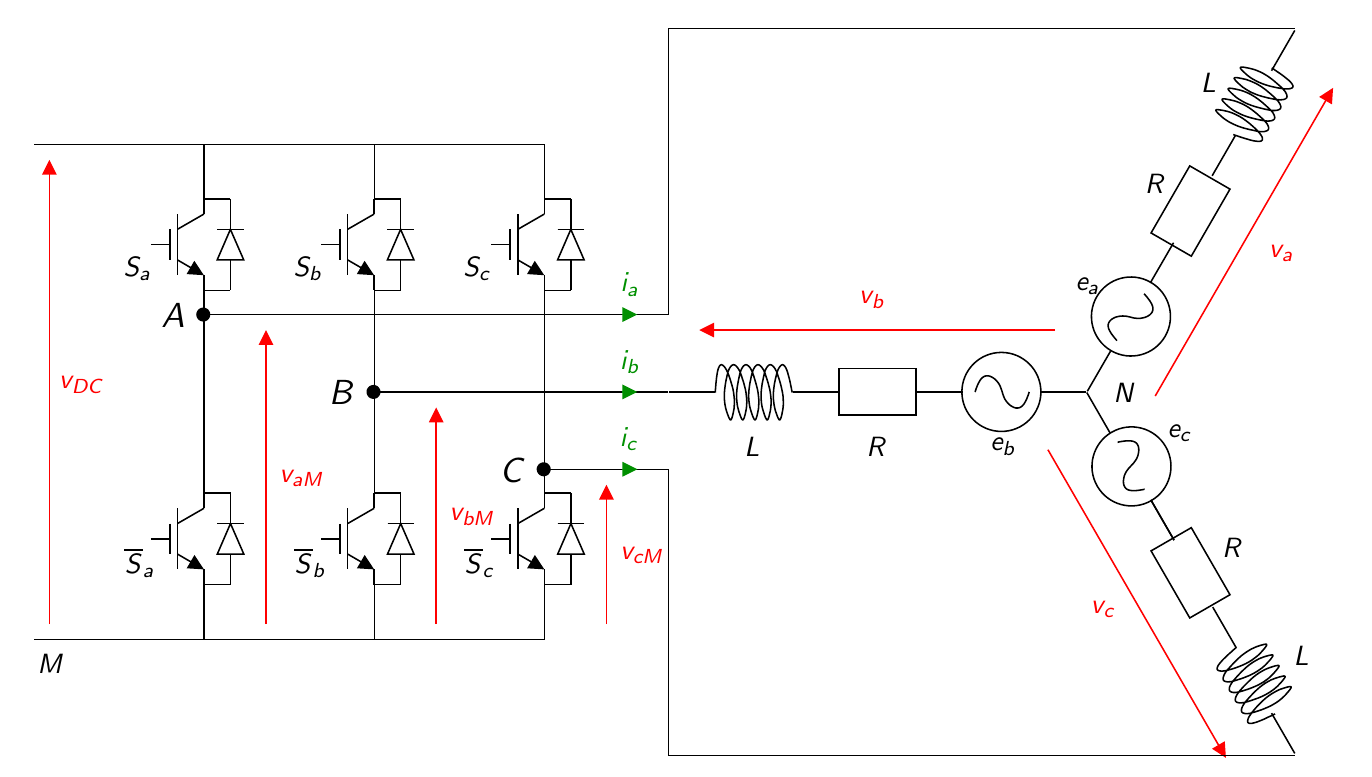
The figure below represents a classical three-arm two-level inverter feeding a three-phase machine with star connection.
Modelling of the inverter
Transistors are considered as switches. The switches on each arm have complementary states. The control signal for the top switch of the arm, denoted \(s_k\) with \(k\in\{a,b,c\}\), represents the state of the \(k\) arm and is defined as follows: \[ s_{k}=\left\{ \begin{matrix} 1 & \textrm{if the high switch is on},\\ 0 & \textrm{if the high switch is off}. \end{matrix} \right. \] The binary state \(s_k\) of the upper switches produces the line-to-ground voltages \(v_{aM},v_{bM},v_{cM}\) such that: \[ \left[\begin{matrix} v_{aM}\\ v_{bM}\\ v_{cM} \end{matrix} \right] = V_{DC} \left[\begin{matrix} s_{a}\\ s_{b}\\ s_{c} \end{matrix} \right]. \label{eq:etataligne} \] So the three arms can generate three independent line-to-ground voltages. The states of the three switches give \(2^3\) possible configurations listed below:
| \(C_0\) | \(C_1\) | \(C_2\) | \(C_3\) | \(C_4\) | \(C_5\) | \(C_6\) | \(C_7\) | |
|---|---|---|---|---|---|---|---|---|
| \(s_a\) | 0 | 1 | 1 | 0 | 0 | 0 | 1 | 1 |
| \(s_b\) | 0 | 0 | 1 | 1 | 1 | 0 | 0 | 1 |
| \(s_c\) | 0 | 0 | 0 | 0 | 1 | 1 | 1 | 1 |
In the case of a balanced star connected machine, we have: \[ \begin{array}{lcl} \mathbf{1}_3^\intercal i_{abc}&=& 0, \end{array} \] and: \[ \sum_{k}v_{k N} = 0, k\in\{a,b,c\}. \] In addition, \[ v_{k N} = v_{k M} +v_{MN}. \] From (4) and (5) one has: \[ \begin{array}{rcl} \sum_{k}(v_{k M} +v_{MN})&=& 0,\\ \sum_{k}v_{k M} & = & -3v_{MN}, \end{array} \] and from (5) and (6), \[ v_{k N} = v_{k M} +v_{MN}=\frac{1}{3}\left(2v_{k M}-\sum_{j\neq k} v_{jM}\right), j\in\{a,b,c\}, \] Finally, from (2) and (7) one obtains; \[ \underbrace{\left[\begin{matrix} v_{aN}\\ v_{bN}\\ v_{cN} \end{matrix} \right]}_{v_{{abc} N}} = \frac{V_{DC}}{3} \underbrace{\left[ \begin{matrix} 2 & -1 & -1\\ -1 & 2 & -1\\ -1 & -1 & 2 \end{matrix} \right]}_{M} \underbrace{\left[\begin{matrix} s_{a}\\ s_{b}\\ s_{c} \end{matrix} \right].}_{s_{abc}} \label{eq:M32} \] Remark: Note that the three-phase voltages \(v_{abc N}\) correspond to the voltages \(v_{abc}\) to be applied to the motor in the rest of the website.
Pulse Width Modulation (PWM)
Here we consider the use of inverter with PWM only. The study of the various forms of MLI has been the subject of much research over the decades (Holtz1992). The aim here is not to review the literature, but to describe the Space Vector Modulation (SVM) solution, in a very simple form to be implemented experimentally. By simply modifying an algorithm, SVM makes it possible to apply higher voltages to the machine phases. The model below represents the motor, associated to the inverter on the hardware side and the modulation for the on the software side.

Average model: For each ideal commutation, the duty cycle applied over a period \(T_{\rm PWM}\), is defined by : \[ \rho_k = \frac{t_{k,\rm ON}}{T_{\rm PWM}}, \] where \(t_{k,\rm ON}\) is the time for which \(s_k=1\). The duty cycle \(\rho_k\) takes values in the interval \(\begin{bmatrix}0&1\end{bmatrix}\). The average voltage value \(v_{k,M}\), is given by: \[ <v_{k,M}(t)>_{T_{\rm PWM}} = \frac{1}{T_{\rm PWM}}\int_0^{T_{\rm PWM}}v_{k,M}(\tau)d \tau = \rho_kV_{\rm DC}. \] On average, the voltage \(v_{abc}\) applied to the motor by the PWM, considering the inverter above, will be: \[ v_{abc} = \frac{V_{DC}}{3}M \rho_{abc}. \] Modulation with harmonic injection:
The inverter is used to apply a desired voltage \(v_{abc}\) to the motor, denoted \(v_{abc}^\#\) (see above), while phase voltage only is accessible (instead of neutral to phase voltage). A simple solution would be to invert the \(M\) matrix given in equation (8), in order to define the duty cycles to be applied to the machine as a function of the desired \(v_{abc}\) voltages. However, the matrix \(M\) is not invertible, because \(\det{M} = 0\). This means that adding the same constant to all the duty cycles has no influence on the voltage between phase and neutral.
A universal representation of PWM is called carrier-based PWM. The duty-cycle \(\rho_{abc}\) can be written as (Vidal2013, Zhou2002): \[ \rho_{abc}= \frac{1}{V_{\rm DC}}v_{abc}^\# + \mathbf{1}^\intercal \lambda, \] where \(\lambda(t)\) is the injected harmonic and \(v_i^\#,i\in\{a,b,c\}\), are the fundamental signals to be applied to the motor. The injected harmonic is referred to as the zero sequence signal .
To ensure that the duty cycles \(\rho_{abc}\) are in the range \(0<\rho_{k}\)<1, the zero sequence voltage can take values in the range (Bowes1997, Hava1998): \[ {\frac{-\min(v_{abc}^\#)}{V_{\rm DC}}}<\lambda<1-{\frac{\max(v_{abc}^\#)}{V_{\rm DC}}}. \] The diagram of the three-phase PWM with carrier is shown in figure below:

A centred aligned PWM is considered. Note \(T_{\rm d}\), the dead time to avoid short circuits in the inverter. The centred aligned PWM prevents switching to take place at the same instant.
Sine PWM is found by taking : \[ \lambda=\frac{1}{2}. \] The maximum voltage, without over-modulation, that can be reached with this configuration is \(V_{\rm max}= \frac{V_{\rm DC}}{2}.\)

Space Vector Modulation (SVM) is found by taking : \[ \lambda=\frac{1}{2}\left(1 -{\frac{\min(v_{abc}^\#) +\max(v_{abc}^\#))}{V_{\rm DC}}}\right).%-{\frac{\max(v_{abc}^\#)}{2V_{\rm DC}}}. \] The maximum voltage, without over-modulation, that can be reached with this configuration is \(V_{\rm max} = \frac{V_{\rm DC}}{\sqrt{3}}.\)

Note that simply adding the functions \(\min\) and \(\max\) increases phase voltages by \(15.47\%\) (corresponding to the change from $ $ to \(\frac{V_{\rm DC}}{\sqrt{3}}\)).


References
(Bowes1997) Bowes, S.-R., & Lai, Y.-S. (1997). The relationship between space-vector modulation and regular-sampled PWM. IEEE Transactions on Industrial Electronics, 44(5), 670–679. https://doi.org/10.1109/41.633469
(Hava1998) Hava, A.-M., Kerkman, R.-J., & Lipo, T.-A. (1998). Carrier-based PWM-VSI overmodulation strategies: analysis, comparison, and design. IEEE Transactions on Power Electronics, 13(4), 674–689. https://doi.org/10.1109/63.704136
(Holtz1992) Holtz, J. (1992). Pulsewidth modulation-a survey. IEEE Transactions on Industrial Electronics, 39(5), 410–420. https://doi.org/10.1109/41.161472
(Vidal2013) Vidal, P.-E., Cailhol, S., Rotella, F., Berkoune, K., Llor, A., & Fadel, M. (2013). Generalized inverses applied to pulse width modulation for static conversion: A first study. 2013 15th European Conference on Power Electronics and Applications (EPE), 1–10. https://doi.org/10.1109/EPE.2013.6634683
(Zhou2002) Zhou, K., & Wang, D. (2002). Relationship between space-vector modulation and three-phase carrier-based PWM: a comprehensive analysis [three-phase inverters]. IEEE Transactions on Industrial Electronics, 49(1), 186–196. https://doi.org/10.1109/41.982262