 GitHub
 YouTube
Motor Control University
PMSM modeling
The motor considered here is a three-phase, star-connected motor. The motor is assumed to be electrically balanced. Magnetic saturations are not taken into account (inductances are independent of current). Finally, the EMF (Electro-Mechanical Forces) are sinusoidal.
Operative part scheme
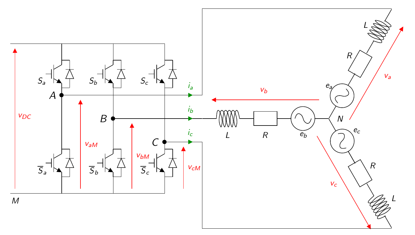
The figure below represents the whole system including the motor and its inverter.
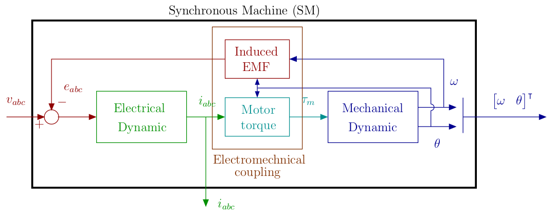
The system can be described with the following bloc diagram.
Classical \(abc\) frame
The electrical equation in the \(abc\) frame is given by: \[ L\frac{di_{abc}}{dt} = v_{abc}-R i_{abc}- e_{abc}, \] with: \[ e_{abc}= -p\phi_f\omega \begin{bmatrix}\sin(p\theta)\\\sin(p\theta-\frac{2\pi}{3})\\\sin(p\theta+\frac{2\pi}{3})\end{bmatrix}, \] where \(i_{abc} = \left[\begin{matrix}i_a & i_b & i_c\end{matrix}\right]^\intercal\) is the stator phase current, \(v_{abc} = \left[\begin{matrix}v_a & v_b & v_c\end{matrix}\right]^\intercal\) the stator phase voltage, \(\omega\) and \(\theta\) are the speed and position respectively and \(p\) the pole pair number. \(L\) and \(R\) and the stator inductance and resistor, \(\phi_f\) the flux constant.
The mechanical equations are given by: \[ \begin{array}{lcl} J \frac{d\omega}{dt}&=&\tau_m-f_v\omega -\tau_l,\\ \frac{d\theta}{dt} &=& \omega, \end{array} \] where J is the inertia, \(f_v\) is the viscous friction coefficient. The electromechanical torque is denoted \(\tau_m\) given by : \[ \tau_m = \frac{1}{\omega} e_{abc}^\intercal i_{abc}. \] and \(\tau_l\) the load torque.

